Follow these five steps to prevent tampering and ensure effective and correct process adjustments for pneumatic components.
Steve Bain, Industry Segment Manager – Food and Beverage, Festo North America
In modern automation systems, the need for frequent process adjustments poses the risk of unwanted device tampering, often referred to in exasperation by plant managers as Unnecessary Knob Twisting (UKT). UKTs result when operators believe they know their machine’s operation better than anyone else and fiddle with a process to make the machine run more smoothly. There are entire Total Productive Maintenance (TPM) programs dedicated to monitoring adjustment points principally due not only to UKTs but also to machines not in optimum condition. Having a consistent machine is a dream for factory managers.
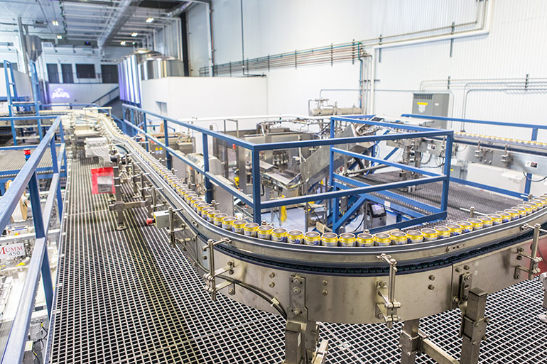
To address this issue and ensure efficient, error-free process adjustments for pneumatic components, plant operations departments can follow a set of five essential steps. These steps include eliminating unnecessary adjustments, leveraging automation to reduce human error, implementing sensors for condition monitoring, maintaining centerlining, and using visual indicators.
Why is tamper resistance important?
OEMs are increasingly designing automated systems to run various product sizes and configurations. Frequent electric and pneumatic process adjustments become necessary in these systems. Changes in pneumatic adjustments are used to regulate flow, pressure, end-stop limits, and machine speed, among other variables. This ongoing need for adjustments, however, opens the door to unwanted device tampering, which can lead to machine malfunctions and process disruptions. The potential for safety risk certainly is also possible, especially if the UKT overlooked the root cause of the problem. There are many instances where a technician flew halfway across the country to diagnose a major problem causing downtime and lost production only to find a flow control valve — that had been perfectly set — had undergone a UKT.

All images courtesy of Festo
Step 1: Eliminate unnecessary process adjustments
The initial step towards efficient process adjustments involves identifying and eliminating adjustments that are unnecessary. The first of these is proper dimensioning during machine design. Using correctly sized components minimizes the need for pressure regulators or flow controls to adjust actuator speed or force. There has always been a tendency in pneumatics to oversize components to ensure enough flow and force. Don’t do it. Not today. Use engineering tools to properly size the components. Using smaller tubing, for example, may eliminate the need for flow control.
Use fixed-orifice flow controls. By embedding fixed-diameter orifices into valve manifolds, actuator speeds can be permanently set, eliminating the need for further process adjustments. Employ modular valve manifolds with multiple valve sizes. This strategy enables optimization based on specific applications, reducing reliance on flow controls.
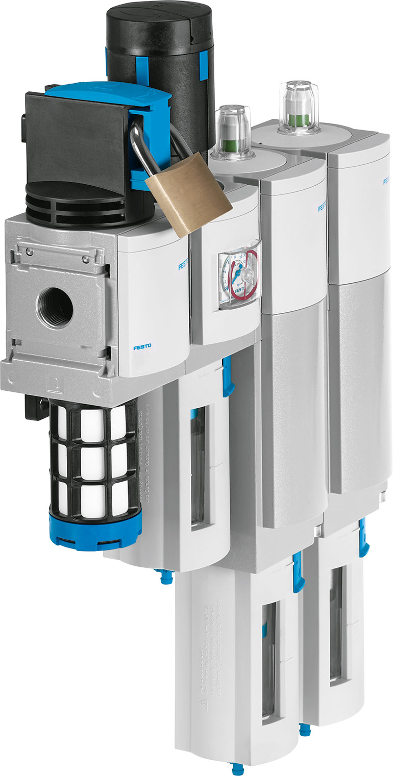
Pneumatic cylinders equipped with automatic, self-adjusting cushioning features ensure optimal performance without the need for adjustment screws. There are regulators that can be locked in position. Once set, these regulators prevent unauthorized adjustments.

Another advantageous outcome of eliminating adjustment points is that most components can be smaller and there are fewer of them — less of everything. This translates into reduced upfront cost. Eliminating adjustment points also reduces maintenance costs as replacing an actuator will not require multiple manual cycles to establish proper flow control and cushioning settings. Simply put, eliminating adjustment points reduces cost, and it costs relatively little to achieve these savings.
Step 2: Use automation to eliminate human error
To minimize the potential for human error, selecting components with built-in automation capabilities is crucial. Use electric control where possible. One example is proportional pressure regulators that automatically adjust output pressure based on signals from a programmable logic controller (PLC). Additionally, advanced electric or servo-pneumatic actuators allow precise configuration of speed and force without pressure regulators or flow controls.

In the past several years, intelligent valve terminals have come onto the market, leading to capabilities that were never easily captured or economically workable. Intelligent valve terminals combine pneumatics and electronics in a single package. These solutions enable digital control and analysis of valve function, flow rate, pressure, and other process parameters.
For air flow control, these systems can integrate flow control valves on actuators and provide tamper-proof travel speeds. Furthermore, they allow the implementation of dynamic flow control. The operation gains the ability through pressure level control to set pressure levels and optimize energy usage and speed control by electronically adjusting the flow control valve setting. Another ancillary benefit of eliminating or minimizing UKTs is energy savings. Intelligent valve terminals can also aid in leakage detection. Separate diagnostic cycles and defined threshold values enable the detection and localization of leaks, which minimizes downtime.
Step 3: Implement sensors for condition monitoring
To ensure the integrity of processes affected by adjustments, implementing sensors for condition monitoring is vital. Start by identifying monitoring opportunities, add sensing (with IO-Link this could not be simpler), and potentially gain the capability to determine when process variables are out of your control. Attributes like supply air pressure, humidity levels and vibration monitoring are candidates. Sensing is essential to assess whether there are any variables trending out of specification.
Other areas to consider include differential pressure monitoring. This can be used in the determination of filter replacements. Pressure sensors and switches that communicate with the PLC can verify automatically whether a process operates within the desired pressure range. Flow sensors are essential for monitoring the amount of consumed air. Flow sensing is vital to knowing whether the process is performing as expected.
Monitoring air flow and pressure is like observing the vitals of a machine. As AI becomes more prevalent in factories, monitoring compressed air at the machine level should be a priority. It is inexpensive and can give immediate feedback.
Step 4: Maintain centerlining
Following the steps detailed above, the operation so far has eliminated adjustment points, automated where it’s been reasonable to do so, and instituted comprehensive condition monitoring to identify anomalies. Now it is time to examine the adjustment points that actually need to be in the system. This is where centerlining comes in.
Centerlining is a methodology that focuses on using established process settings to ensure consistent line operations. Centerlining works to decrease product and procedure inconsistencies by optimizing machine effectiveness.
A packaging machine may have mounted rulers at each adjustment point to determine where some component needs to be aligned. Additionally, manufacturers can use counters on rotary knobs for the operator to dial in the exact number where the setting should be at a particular time. Another good example is a flow meter that can be dialed to the exact amount of air documented for the process at the time required.
To ensure consistency, use numerical scales for manual adjustments. Seek out flow control components with position markings or digital flow meters, labeled adjustment rings, or integrated displays to achieve the desired flow rate accurately.
Step 5: Take advantage of red and green visual indicators
Finally, there may be some adjustment points that are not cost-effective or even possible to eliminate, automate, or centerline. To facilitate error-free process adjustments, opt for pneumatic components equipped with red/green indicators. These features offer a quick and easy way to validate whether processes are performing as expected. There are adjustable red and green ranges that provide an extra level of safety for monitoring compressed air usage, allowing immediate identification of pressure within or outside the permitted tolerance range. Even untrained personnel can recognize when something is out of range and alert maintenance.

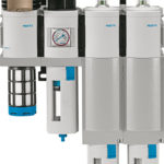
There are air filtration components, including pressure regulators, on/off valves, soft-start valves, pressure sensors, and flow sensors that feature scales that display red/green ranges. Some flow sensors even use illuminating displays that turn red to indicate when the flow is beyond the desired range.
Final words on UKTs and tamper proofing pneumatic systems
Process adjustments are an integral part of automation systems, but they must not lead to unwanted device tampering or process disruptions. By following five steps, which emphasize proper sizing, the use of components with automatic adjustment capabilities, implementation of condition monitoring, centerlining, and utilization of visual indicators, plant operations departments can boost efficiency and accuracy for their pneumatic components. Ultimately, this approach reduces costs, enhances productivity, reduces errors, and ensures smoother packaging line operations.
Festo
festo.com



Leave a Reply