• Skip to primary navigation
  • Skip to main content
  • Skip to primary sidebar
  • Skip to footer
  • Advertise
  • Subscribe

Pneumatic Tips

Tips, Trends, Resources, News and Information

  • Blog
  • Industry News
  • Air Preparation
  • Engineering Basics
  • Components
    • Actuators
    • Cylinders
    • Fittings
    • Gears
    • Grippers
    • Pumps
    • Air Compressors
    • Tubing
    • Vacuums
    • Valves
  • Pressure Sensing
  • Design Guide Library
  • Classrooms
    • Pneumatics Classroom
You are here: Home / Air Preparation / Compressed air fail: Outlet pipe size

Compressed air fail: Outlet pipe size

April 12, 2024 By Paul Heney

Share
Fig. 1. The outlet flange on this large air dryer is 6-in. size, yet the connection piping installed is only 4-in. This is a sign that the smaller piping may be too small (it was).

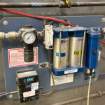
A compressed air auditor was assessing a compressor and dryer installation within a compressor room and noticed something strange. On a large air dryer, the outlet flange was of 6-in. size, yet the piping used to connect the compressors and filters to the air dryer was only 4-in. Further to this, the long piping link connecting to the main plant distribution was also 4-in. A piping size transition was installed to connect the small piping to the large flange on the dryer as shown in Fig. 1.

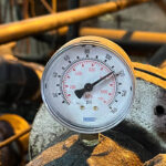
Using measurement instruments, the auditor measured the pressure drop between the compressor discharge and the outlet to the system and found a possible problem. During low loads — when only one compressor was running — the pressure loss was minimal. However, when all the compressors within the compressor room ran at peak capacity, the pressure differential was more than 10 psi, which is excessive for an industrial compressed air system.

Pressure loss in a compressed air system, caused by friction, varies exponentially with square of the flow change. So even a small change in flow can cause a large change in pressure differential. Doubling the flow across a 3-psi piping restriction will cause a the pressure differential to rise to 9 psi. In this case, the pressure loss was as high as 12 psi at peak flows, causing the compressor discharge pressures to be set higher than normal to overcome this loss. The higher the compressor discharge psi, the more power they consume. The relationship is about 1% more power for each 2 psi in higher pressure.

Flow meters were installed on this system so the flow velocity could be checked. It was found that the flow velocity during peak production was about 50 feet per second, much higher than desired. This was causing significant pressure loss. Typical pipeline velocity in a well-designed system maintains peak flows of between 20 to 30 feet per second within the compressor room. A good way to calculate pipeline velocity is to use USDOE’s Measure Tool.

There is often a good reason why air compressor and dryer outlet flanges are sized the way they are, but be aware not to reduce piping size to cause excessive restrictions.

You may also like:


  • Compressed air fail: Breathing air purifier

  • Compressed air fail: Remote cooler install

  • Compressed air fail: Nozzles check

  • Compressed air fail: OSHA blow gun regulations

Filed Under: Air Compressors, Air Preparation

Primary Sidebar

Fluid Power World Digital Edition

Fluid Power World Digital EditionBrowse the most current issue of Fluid Power World and back issues in an easy to use high quality format. Bookmark, share and interact with the leading design engineering magazine today.

RSS Featured White Papers

  • eBook: Practical Guide to Pneumatics
  • Saving energy and service cost with electric linear systems
  • White Paper-How to Design Efficient Pneumatic Systems!

Fluid Power Design Guides

fluid
“pt
EXPAND YOUR KNOWLEDGE AND STAY CONNECTED
Get the latest info on technologies, tools and strategies for Fluid Power Professionals.
Hose Assembly Tips

Footer

Pneumatic Tips

Fluid Power World Network

  • Fluid Power World
  • Hose Assembly Tips
  • Mobile Hydraulic Tips
  • Sealing and Contamination Tips
  • Fluid Power Distributor Lookup

PNEUMATIC TIPS

  • Subscribe to our newsletter
  • Advertise with us
  • Contact us
  • About us

Copyright © 2026 · WTWH Media LLC and its licensors. All rights reserved.
The material on this site may not be reproduced, distributed, transmitted, cached or otherwise used, except with the prior written permission of WTWH Media.

Privacy Policy