

By Eric Cummings • Global Industry Manager – Safety • ROSS Controls

While safety standards have been updated by safety controls engineers, pneumatic systems present a unique challenge. In following the ISO 13849 standard, which uses redundancy and diagnostics for higher-level circuits, it is important that designers and integrators understand the specifics of the valves selected for the system.
It is easy to create a pneumatic circuit that looks clear and simple on paper but when implemented, may not accomplish the desired outcome when a single channel failure occurs.
One typical application example is a customer who wants a machine’s air to exhaust when the operator breaks the light curtain in front of the point of operation. Removing the system air would stop the hazardous motion. They currently accomplish this with a standard single channel 3/2 normally closed valve.
Their solution for providing an additional exhaust path for the air causing the cylinder motion was to add a 2/2 normally open valve downstream of the current 3/2 valve.
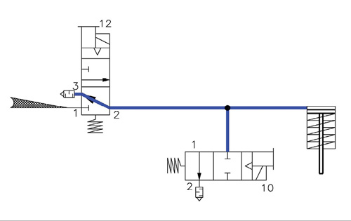
This 2/2 valve in Figure 1 would remain energized during normal operation but would de-energize when the light curtain was broken and provide a redundant exhaust path. If the 3/2 valve were to stick in the actuated position, the 2/2 valve would allow the air to exhaust from the system. However there are two primary shortcomings with this system as designed.
The first issue is that there is no system monitoring. If the 2/2 valve was to stick in the actuated position as in Figure 2, the 3/2 valve would still be exhausting the air and providing correct machine function. This would not be noticed. Adding a pressure switch to the pipe being exhausted would also not indicate if this failure occurred. Only monitoring the exhaust time through a transducer or the stopping time of the machine would show indication that the air was not exhausting through the parallel exhaust passages and that a fault had occurred. However, it would take an accumulation of faults for this hazard to exist considering the failure mode.
The second issue is the larger problem. Most 3/2 normally closed valves will have a similar in-to-out and out-to-exhaust flow capacity. A valve that supplies air at 3 CV typically exhausts air at a similar flow rate. This flow rate depends on the individual valve size and internal design. Assuming a ½ in. line and 3/2 valve with a supply of 3 CV for this system, the designer added a similar sized ½ in. 2/2 valve with a similar flow rate, thus doubling the system exhaust capacity. But what happens if the 3/2 normally closed valve fails in the actuated position?

If the system is fully pressurized and both valves are given signals to deenergize but the 3/2 valve sticks energized as in figure 3, it is still supplying 3 CV of air flow to the system. Even though the 2/2 valve is exhausting 3 CV of system air flow, the original air pressure in the system would remain relatively unchanged and motion would continue. A simple way to consider this would be thinking of your bathtub. If full of water with the faucet flowing and the drain open there is minimal change in the water level.
In this case a single channel failure mode has compromised the safety system. Adding diagnostics to each valve would provide feedback but would still not eliminate a single channel failure mode, which leaves this circuit at less than category three. A better solution would be to add two 3/2 normally closed valves with diagnostics or an integrated dual 3/2 exhaust valve.
ROSS Controls
www.rosscontrols.com
Leave a Reply