


Reducing size and energy consumption is paramount in most any-market application today, particularly in orthoses, which require compact power and control.
To this end, a novel miniature proportional valve for controlling airflow in pneumatic systems is being developed at the University of Minnesota. The valve is expected to require two orders of magnitude, less power than most conventional valves on the market; the design goal is to keep the normally closed valve in the fully open state with only 5 mW of power. Its intended flow capacity is 40 slpm when venting from a pressure of 6 to 5 bar and its maximum design pressure is 100 psi. The intended package size is only 7 cc.
One of the goals of CCEFP research is to develop portable human-scale fluid power solutions. This valve project was inspired by an ankle-foot orthosis being developed by Professor Elizabeth Hsiao-Wecksler at the University of Illinois at Champaign-Urbana. The orthosis is an active medical device to help fix abnormal walking gaits. It uses a small CO2 bottle and a rotary actuator to assist foot rotation. The entire package fits under the user’s pant-leg. As it is attached to a person’s leg, reductions in size, weight and power consumption are paramount. It is the hope of the project team that all three parameters can be absolutely minimized by going to a micro-scale device, as is outlined below.
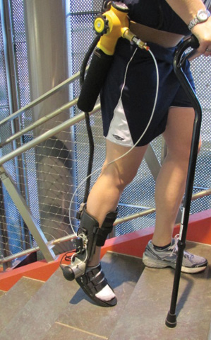
Photo courtesy of Professor Elizabeth Hsiao-Wecksler, the University of Illinois at Champaign-Urbana.
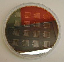
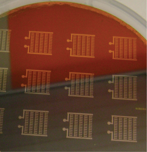
The remarkable specifications of this valve are achieved by exploiting MEMS technology. Using MEMS batch fabrication will drastically reduce manufacturing costs by being able to someday create hundreds of these valves on a single silicon wafer. This means that in addition to the size and power benefits already noted, the new valves are also expected to be low cost. And while the valves are also lightweight, a larger weight reduction is expected to come through downsizing the battery required to power the valves.
Designing microvalves using MEMS technology is not new; it has been studied extensively over the past 30 years. However, traditional microvalves have been restricted to the realm of micro-fluidics, where flows are on the order of milliliters per minute and pressures are very low. Therefore, they are not applicable to most fluid power applications. This project is only the second to apply MEMS technology to a larger scale valve (the first being a servovalve developed by DMQ Microstaq).
The microvalves are made up of two separate plates, an orifice plate and an actuator plate, which are fabricated individually and then assembled together. The actuators have cantilever architecture and are made of piezoelectric material. The piezoelectric material is lead zirconate titanate (PZT), which was chosen due to its excellent piezoelectric coefficient, which is an indication of the amount of tip deflection per unit of voltage applied. These beams are “bimorphs,” meaning they have two active layers of piezoelectric material and therefore significantly more deflection than just a single layer (“unimorph”).
Each piezoelectric layer is sandwiched between two platinum electrodes and is activated by imposing a voltage across the material. By applying reverse voltages to the two piezoelectric layers, the top layer contracts as the bottom layer expands, causing maximum tip deflection. Proportional displacement is achieved by simply applying a variable voltage.
The research approach to creating this valve began with the construction of a much larger, proof-of-concept “meso-scale” piezoelectric valve. This valve is roughly 20 times larger than the MEMS valve. The piezoelectric actuator was bought off the shelf and is roughly 100 times larger than the beams on the MEMS valves. The orifice plate is made out of steel rather than silicon and has large enough orifices to be precision machined outside a clean room. This valve was characterized using an experimental test stand designed and built at the University of Minnesota. A capacitive displacement sensor is embedded in the housing and interacts with a grounded copper pad on the top of the actuator. This system was used to validate the valve concept, as well as test orifice flow models. A similar valve was introduced to the market in 2012 by a company unrelated to this project, showing that the meso-scale concept is commercially viable.
As for the MEMS valve, a successful fabrication process for both the orifice and actuator plates has been established. The orifice plates were challenging as the orifices have an aspect ratio of up to 20:1. The actuator plates were also challenging, as the beams are a mere 2 µm thick, and therefore extremely fragile.
Furthermore, PZT is prohibited in most micro-fabrication facilities nationwide (unfortunately including the University of Minnesota) due to lead contamination concerns.
With both plates designed, fabricated and tested, the final frontier will be assembling them together into a complete valve. This too will be challenging as conventional clean room bonding techniques apply to clean, level, similar surfaces on a full wafer level. As the intent is to bond two drastically dissimilar materials, with varied topology, including extremely fragile and thin beams, and on a device much smaller than a wafer, there are challenges to overcome.
Contributed by Erik Hemstad, Master’s student, and Nebiyu Fikru, PhD candidate, at the University of Minnesota. This research has been supported in part by the NSF-ERC Program “Center for Compact and Efficient Fluid Power” (EEC-0540834). Please contact Prof. Thomas R. Chase, trchase@umn.edu, for further information.
Great article! New technologies that reduce energy loss and weight for orthosis design can be achieved with the application of recent materials and construction processes improvements
http://www.hydraulicandpneumatics.com