Clean air is crucial for optimal pneumatics

February 15, 2011 by  
Filed under Air Preparation, Featured

Liquid water, water vapor, particulates and oil can all interfere with proper compressed air operation. 
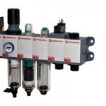
Removing moisture and contaminants ensure that the system does not experience premature wear or damage.

norgren combined filter regulator

For optimal pneumatics performance, it is usually necessary to reduce the pressure of air leaving the compressor and filter out water, oil and contaminants. For some applications, clean oil needs to be added to the air to lubricate downstream equipment. This unit shows, left to right, a combined filter/regulator for general filtration/air pressure regulation, a coalescing oil removal filter and a lubricator.

Pneumatics is a versatile, proven technology for powering or controlling the operation of an amazing number of applications, from neo-natal respirators to building-size industrial equipment. The range of pneumatics capabilities is illustrated by the variety of typical systems, their uses and requirements.

• General pneumatic circuits (e.g. directional control valves and cylinders in machine cleaning, air motors and high-speed tools)
• OEM machines
• Breathing air
• Heavy duty lubrication
• Direct injection lubrication, such as required for conveyor chains
• Oil-free applications like paint spraying or film processing
• Critical pressure control and instrumentation
• Motion control for industrial automation or equipment operation
• Continuous processes like those in paper mills or chemical plants

While the configuration of pneumatic components for each of these systems varies, they all require air of the proper quality, temperature and pressure to function most productively. The air leaving a compressor is hot, dirty and wet, and is generally at a higher pressure than desired. Before this air can be used, it needs to have contaminants removed, pressure reduced and, in many cases, oil added to lubricate downstream equipment. This article examines the first requirement: removing moisture and contaminants.

Liquid water
Air exiting the compressor outlet will contain water vapor, but as the air cools, the moisture condenses. The amount of water vapor in any given volume of compressed air is directly proportional to the air temperature and inversely proportional to the pressure, so there is more liquid water when the temperature is lowest and the pressure highest. This is the point where removing it is the most efficient. An aftercooler should be used to cool the air coming out of the compressor to within 8º C of the temperature of the water entering the after cooler for most efficient water removal.

At this point, the outgoing air should be piped to a receiver in the coolest location available, definitely not within the compressor house itself. Further cooling—and condensation—may occur in the distribution mains. These should be laid out with a pitch in the direction of air flow, so gravity and air flow will carry the water to drain legs. Except for these drain legs, all other air take-off points from the distribution mains should be taken from the top of the main to prevent water from entering the take-off lines.

As discussed earlier, water condenses (and is most efficiently removed) at high pressure, so anything that produces a pressure drop in the distribution system should be avoided. Filters should be located upstream of any pressure-reducing valves.

Maintaining consistent pressure also conserves energy, helping to control costs. Make sure to properly size piping and eliminate complex flow paths with undue bends.

Water can be removed using drip leg drains, automatic drain valves or filters. These devices should be located where liquid water is present in amounts large enough to be removed. Because air may cool as it passes through distribution mains and branch lines, it is more effective to install smaller individual filters as near to the actual point of air usage as possible, rather than rely on one large filter at the air receiver.

Water vapor
A system properly designed to remove liquid water will still not remove moisture from the air, and this moisture can condense later in the process. If the application requires complete freedom from water contamination, then the water vapor content must be reduced to the point that the dew point is lower than any temperature to which the air in the system will be exposed.

To remove water vapor from a compressed air system, air dryers must be employed. Dryers are most efficient at the lowest possible temperatures, and performance is diminished when air is contaminated by water, oil or water/oil emulsions, so dryers should always be used in conjunction with filters and coolers.

There are three types of dryers: refrigerant, regenerative adsorbent desiccant and deliquescent absorbent. (See Table 1, Dryer Comparison.) Here are some considerations for making the most cost-effective dryer choices.

dryer comparison table

Does your process truly require dry air? Air dryers are most commonly needed in general industrial applications where high ambient temperatures exist.

Do not specify extremely low dew points if the process does not warrant them.

Limit the volume of air being dried to that actually needed for the particular process, plus some capacity for expansion. For example, only one area of a process plan may require a dryer.

General recommendations for air drying can be difficult, since this depends on the temperature of the compressed air main adjacent to the operation, the level of pressure reduction and air flow rate. It also depends on the relative humidity and ambient temperatures of the local environment.

Solid particles
Particulates enter every compressed air system, either through ambient air intake, corrosion, or carbon build-up. Dirt particles can range in size from a fraction of a micron to several hundred microns, (See Table 2) but generally fall into two categories: coarse (40 microns and above) or fine.

particle size ranges table

Most normal airline filters will remove coarse particles. Fine filtration in the region of 10-15 microns is normally required for high-speed pneumatic tools or process control instrumentation. Filtration of 10 microns or finer is essential for air bearings and miniature pneumatic motors. Even finer filtration may be needed for paint spraying, breathing air or food-related applications. These require high efficiency (oil removal/coalescing) filters. Standard airline filters should be used as pre-filters to avoid overburdening the finer filters with coarse particles and triggering premature failure.

Oil as a contaminant
The principle source of oil contamination in a compressed air system is the compressor. Oil lubricates the compressor, but by the time it emerges with the compressed air, it has lost any lubricating capability and in fact is an aggressive contaminant that must be removed.

Normal airline filters will remove enough oil to leave the air suitable for most pneumatic tools and cylinders, but certain applications require completely oil-free air. Oil-free compressors eliminate oil but not water and dirt. So it can be more economical to use lubricated compressors with after coolers and standard airline filters and fit high efficiency oil removal filters only at the points in the system where oil-free air is absolutely required.

Norgren general airline filter

A general airline filter to remove water and large particles should always be located upstream from a coalescing filter to prevent clogging filtration media. On this general purpose/coalescing filter combination, when the filter elements become saturated to the point that air pressure drops, the green indicator on top shows red, signaling the operator that the element needs to be changed.

Oil in compressed air systems can exist in three forms, oil/water emulsions, aerosols or oil vapor. While emulsions can be removed by standard airline filters, more sophisticated filtration is required for aerosols or vapors.

Aerosols are small oil particles suspended in the air. Approximately 90% of these are between 0.01 and 1 micron—too small to be removed by the centrifugal action of standard airline filters. Special coalescing filters are required, and these should be protected against particulate and water contamination by airline filters mounted immediately upstream.

For most processes, removal of oil vapor is unnecessary, since quantities are minute. Exceptions include food or beverage processing, pharmaceuticals or breathing air applications.

The most common method of removing oil vapor is to pass the air through an adsorbing bed, usually comprised of activated carbon, after it has been through a pre-filter and a coalescing filter. Note: this system will not, as is sometimes thought, remove carbon monoxide or carbon dioxide.

Filter selection
Once all the contaminants have been considered, the degree of cleanliness of air for each part of the industrial plant or process can be determined. Table 3 shows the levels of contaminants allowed in each class of air quality as defined by ISO 8573. Employing the correct filters in the right locations can keep energy and maintenance costs to a minimum.

air quality classifications iso 8573 table

recommended air quaility for various applications table

Table 4 shows typical air quality class requirements, and thus recommended filtration levels, for various applications. Also, selecting a filter rated for volume of air required is critical because undersized, inappropriate filters drive up energy costs.

When designing filtration to clean compressed air, be sure:

• The correct type of filter and element rating is selected for particle removal.
• Liquid removal is efficient and re-entrainment is not possible.
• It is easy to maintain the filters and remove liquid condensate.
• There is easy visual monitoring of condensate or filter elements for proper function or prompt maintenance. This may be a pressure drop device, liquid level indicator or transparent bowl.

With the system in place to remove contaminants from compressed air, designers can move on to the challenges of optimizing pressure and adding lubrication. Correct air preparation is the best way to get maximum performance from any pneumatically controlled system.

Norgren, Inc.

Electric Rod Actuators Challenge Pneumatic Cylinders

September 15, 2010 by  
Filed under Actuators, Cylinders, Equipment

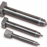
The US actuator specialist Tolomatic has developed a range of electric rod-style actuators as an economical alternative to non-repairable pneumatic cylinders, and for automating manual processes. The ERD actuators deliver forces of up to 334N at speeds of up to 1,016mm/s.

pneumatic actuatorsAaron Dietrich, Tolomatic’s electric products manager, says that the patent-pending actuators (shown above) “provide an alternative to pneumatic cylinders with the added benefit of greater control of speed, acceleration and force”. They also offer an “affordable option for automating manual processes”.

The round-bodied electric actuators are available in sizes equivalent to 5/8, 1 and 1.5-inch bore non-repairable pneumatic cylinders. They accept Nema 11, 17 or 23 frame stepper and servomotors, and the acme leadscrews are available in three lead sizes per model to optimise speed or force.

The actuators, which come with metric-threaded rod-ends, can accommodate six different sensing or switching technologies including reed, solid-state PNP or NPN, normally open, flying leads or quick-disconnect. The switches are activated by a magnet inside the thrust tube.

www.tolomatic.com

TRD Manufacturing Introduces the MH Series and TAS Cylinders

September 3, 2010 by  
Filed under Cylinders, Equipment, Featured

Machesney Park, IL – TRD Manufacturing, a Bimba Company, announced the introduction of the new MH Series and TAS Series Cylinders designed to deliver more reliability in heavy-duty industrial operations.

MH Series Cylinder Cut Away
MH Series

The MH Series are medium pressure hydraulic cylinders rated for 675 to 1500 psi (depending on bore size). The TAS Series Steel Pneumatic Cylinders are rated for 250 psi air and 400 psi hydraulic (with TH option). Both models are available in bore sizes 1.50”, 2”, 2.50”, 3.25”, 4”, 5”, 6” and 8”.

TAS Series Cut Away
TAS Series

Standard features include a heavy-duty rod wiper, seals, wear band, chrome plated I.D. tube and more. Rod locks, stop tubes, center supports, stainless steel piston rods and high impact pistons are also available as performance options. Accessories include clevis, pins, mounts and alignment couplers, with up to a 5” thread size.

TRD Manufacturing
www.trdmfg.com

Bimba Manufacturing
www.bimba.com

New Modern Polyurethane Makes Great Material For Pneumatic Seals

June 14, 2010 by  
Filed under Equipment, Seals

Polyurethane’s elastic properties, mechanical strength and wear resistance make it a good material for pneumatic seals. When the polymer’s composition and design development are tuned to the specific demands of pneumatic applications, modern polyurethane pneumatic seals shift operating limits to new levels. This has been validated by rigorous testing and validation.

Pneumatic actuators are key elements of material-handling and automation systems used for moving, clamping and positioning goods, boxes, flaps, gates, etc. A typical pneumatic cylinder (Figure 1) contains several static and dynamic seals. The dynamic seals are:

Double-acting piston seal (often two U-cup seals) Rod seal and dirt wiper (often combined in one element) Two cushioning seals for the adjustable pneumatic end cushioning.  The dynamic seals have to work well with: Oil-free compressed air using only the minimal grease lubrication that was applied during cylinder assembly Operating pressures to 100 psi with excursions to 360 psi during cushioning Creep velocity of 3+ ft./sec. A temperature range of -4°F to +176°F With a typical cumulative lifetime travel of at least 4,000 miles, the area of dynamic contact must maintain grease lubrication. A flexible sealing lip geometry provides low radial forces, and a rounded contact area allows the lip to float on a grease film.

If hydraulic seals were used in pneumatic cylinders, the high radial force and sharp sealing edges would scrape the grease away from the contact area. The grease would collect at the ends and the ensuing poor lubrication would result in high friction, heavy wear and shortened useful life.

Seal design refinedThe seal design follows the principles described above. Additional features ensure proper function under any operating condition.

Piston seal: U-cup-type piston seals have been used in pneumatic cylinders for many years. The design in Figure 2 has several special features. It has a thin connection between sealing lip and body to achieve low radial force. Toward the contact area, the lip is larger to give stability under pressure.

Notches at both lips and on the outer diameter of the back side avoid malfunctions. The notches on the side of the outer sealing lip ensure proper activation when the pressure increases. Notches at the outer diameter of the back and on the inner lip act as pressure-release channels in case pressure is trapped between the two U-cups in a double-acting piston. Without these notches, a pressure trap, together with friction, can tilt the seal in the groove, which results in an inoperable cylinder. The rounded contact area of the sealing lip was optimized by finite element analysis to ensure good function over the whole pressure range.

A polyurethane material was developed for the specific demands of pneumatic applications. The 83 Shore A hardness is relatively low to minimize the radial force. With its good compression set, low friction and extraordinary wear resistance, it provides the preconditions for good functional properties and long service life.

Rod seal: The rod seal is designed to suit grooves for pneumatic cylinders to ISO 15552. The seal has a sealing lip and a dirt wiper lip, and is fixed by a retainer «nose» at the outer diameter. The seal can be mounted into an unsplit gland by pushing it into the bore until the retainer nose snaps into the mating groove of the housing bore. The outer, static sealing lip is chamfered for ease of installation.

As the seal is fixed only by its retainer nose, the seal material must be stiff enough to withstand the axial forces of pressure and friction. Therefore, a harder material (94 Shore A) is used to maintain the proper seal orientation.

Cushioning seals provide smooth piston movement at the dead-end positions. The cushioning seal (Figure 5) works better than O-rings. The specific design features are:

Dynamic sealing lip gives good tightness and low friction Axial sealing edge with check valve functionality Combined notches at the lip side and on the outer diameter to allow air flow

The cushioning seal is active only at the end of the stroke. A pressure chamber, which is formed between cushioning seal and piston seal, works like an air pillow to absorb the kinetic energy smoothly. To ensure that the cushioning seal doesn’t affect movement when the cylinder reverses direction, the seal has an integrated check-valve function that forces the pressure to act on the full cylinder area. If O-rings are used as cushioning seals, the movement is delayed because the air pressure can’t act on the full cylinder area until the cushioning rod has moved out of the O-ring. Tests validated performanceA test program performed with commercially available pneumatic cylinders confirmed the material and design-development efforts. The cylinders were equipped with a rod seal-scraper, two piston seals and two cushioning seals. The test program included:

High-pressure test Bursting pressure test Low-temperature test Temperature cycling test Minimum speed test Endurance test The test procedures reflected harsh, but realistic, operating conditions using oil-free compressed air with an oil content < 0.01 mg/m3 (class 1 to ISO 8573-1). Testing monitored two indicators of seal functionality: the leak rate at two pressure values (29 psi and 145 psi) and the break-off pressure in both directions. The break-off pressure is the minimum pressure needed to move the cylinder. It’s different for outstroke and return stroke because the pressurized area of the cylinder is smaller on the rod side.

High-pressure test: This test reflects the situation at peak pressure during the cushioning cycle. To avoid having to produce and dissipate excessive energy, the test equipment included a pressure intensifier to generate an operating pressure of 360 psi. The cylinders have a short stroke of 0.59 in. to simulate only the cushioning cycles. Special high-pressure lines and high-pressure valves are used.

After 100,000 cycles, the sealing function wasn’t compromised by physical damage, seal wear or leakage. Break-off pressure was the same as when new. The sealing system proved its robustness and reliability even under extreme pressure peaks during the pneumatic end-cushioning cycle.

Bursting pressure test: This test confirms seal robustness and safety in case of abnormally high pressure. For the rod seal, this test shows the safe fixation by the retainer nose. The cylinders functioned at the target pressure of 725 psi without problem. The first leakage occurred at 942 psi, when the rod seal was partly extruded out of the housing, but no seals were damaged. After re-installing the rod seal, the cylinder was fully functional with a leak rate and break-off pressure the same as new.

Low-temperature test: This test shows the minimum temperature under which the cylinder functions properly. The cylinders were installed in a temperature chamber and connected to an external measuring station to enable measuring of leak rates and break-off pressure. An additional air dryer helped avoid water accumulation in the system. After cooling down the system, the measuring was done quickly to avoid frictional heating that would affect the result.

The low temperature limits of the piston seals depend on their location on the piston, although the two piston seals are identical. The piston seal at the bottom of the cylinder is the most critical position because it is measured with the rod extended, when the guidance clearance causes a misalignment between the piston and the cylinder tube. The piston seal at the rod side is measured with the rod retracted, when piston and cylinder tube are in good alignment. Under such good conditions, the piston seal works well at lower temperatures. So, the degree of misalignment leads to a low-temperature limit between -4°F (piston seal bottom side, rod extended) and -22°F (piston seal rod side, rod retracted). The rod seal is tight down to -40°F because the volume shrinkage from temperature reduction helps to keep the lip in sealing contact.

To summarize, testing showed that the pneumatic cylinder remains fully functional down to -4°F under worst-case conditions, and down to -13°F under normal conditions.

Temperature cycling test: This test cycles between minimum and maximum operating temperature to show the seal material’s ultimate behavior. The test equipment was the same as for low-temperature testing. Temperature cycling revealed no leakage and no change in break-off pressure, which proves that frequent changes of operating temperatures don’t affect the service life.

Minimum speed test: This test explores a cylinder’s operation at creep velocity. The cylinder, equipped with a side-load weight, is pressurized on one side while a throttle valve on the other side is closed until the cylinder begins to exhibit stick-slip mode.

The test results demonstrate how a sealing system can be optimized with material technology and design knowledge. The thorough consideration of functional aspects and use of latest development tools produce better performance. The material development, focused on the specific demands of pneumatic applications, was the second component of a high-performance polyurethane sealing system. Pneumatic equipment manufacturers and end users can be sure of the best functionality under extreme conditions, absolute reliability and outstanding service life. Thus, the costs for replacement and consequential costs from production shutdowns can be reduced.

screamnews.com

Self-adjusting Cushioning for Pneumatic Cylinders

May 26, 2010 by  
Filed under Cylinders, Equipment, Industry News

No more need for toing and froing when you are adjusting the cushioning of pneumatic cylinders. Festo’s self-adjusting cushioning PPS makes commissioning easier and also saves time. It makes it possible to achieve a dynamic but gentle cushioning action into the end positions of cylinders without the need for manual intervention.

Festo HM0609 Standard Cylinder
Festo round cylinders DSNU are now available with self-adjusting pneumatic cushioning. (Photo: Festo)

Until now, users always needed to adjust the end-position cushioning integrated into cylinders manually, with the risk of slow cycle times or excessive noise generation. Manual adjustment of end-position cushioning also takes time; this makes commissioning a very long drawn-out process in the case of installations with a lot of drives requiring cushioning.

Without any need for manual interventions, self-adjusting cushioning PPS from Festo now ensures an optimum cushioning action every time, even if parameters such as friction and pressure change. It also reduces the acceleration forces acting on components and workpieces. This cuts down wear and minimises time-consuming vibration. What is more, in comparison with shock absorbers, self-adjusting cushioning is less expensive and more robust. This unique cushioning, not offered by any other supplier, is now available with the Festo round cylinder DSNU, of which millions of examples have already been sold.

Festo HM0609 Standard Cylinder 2
With Festo’s self-adjusting cushioning PPS for round cylinders DSNU, longitudinal slots on the inside of the cylinder discharge exhaust air in a controlled way, thus making it possible to achieve dynamic but gentle cushioning action into the end positions without the need for manual intervention. (Photo: Festo)

The DSNU-PPS variant with self-adjusting cushioning described above is not the only member of the DSNU range to offer impressive performance. In addition to the basic, standardised version, DSNU is available with four different mounting options, created by combinations of a total of three different bearing caps and four end caps. This include end caps of block design for direct mounting or with flange threads, end caps with threaded lugs and swivel bearings, with air supply connections that are lateral or in-line with the cylinder axis. The advantages for customers are: no need for costly special solutions, more flexibility during system design and less work when ordering. To ensure that ordering remains transparent and simple, the wide variety of available piston diameters, stroke lengths, functions and variants can be selected with just a single order code. Further variants are available with a through piston rod, heat-resistant seals and clamping units.

The DSNU covers all the applications within the ISO 6432 standard but also goes well beyond this. It will appeal to all users who place the most stringent requirements on round cylinders with regard to quality, a wide choice of variants, availability and price/performance ratio. The well-known long service life of Festo cylinders helps ensure system availability and thus guarantee maximum productivity.

Festo
www.festo.com