

 Careful consideration to the sizing of the components feeding an end use is important. If not done correctly, the performance of the device can be negatively affected.
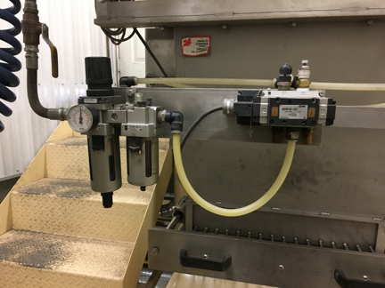
Too often, low pressure problems will occur because a plant has selected a filter, regulator, lubricator (FRL) combination that is a standard size for all devices in the facility. This saves inventory costs because all the spare parts are the same, but depending on the characteristics of the demands, there could be performance issues cause by excessive pressure drop across undersized components.
If the compressed air device has a “flow static” characteristic, then the pressure only needs to be held above the minimum required level at the end of an operation. For example, a cylinder is moved from one position to another to hold a piece in a clamp. In this case, the pressure needs to be adequate only when the clamping action takes place, with minimal flow, not while the cylinder is moving positions.
A “flow static” application is something that requires the minimum pressure to be maintained at the point of use at the same time as peak flow. An example of this might be a cylinder with a constant load that might need to stroke from one position to another in 0.5 second.
For the flow static application, smaller components can be used; it doesn’t matter much what pressure drop occurs in the filter regulator, as long as the proper pressure occurs at the end of the stroke to apply the required force.
For the flow dynamic application, careful design must take place to ensure the combined total of all the pressure drops across the filters, regulator, lubricator, supply hoses and connectors does not allow the pressure to fall below the minimum required pressure at the point of use.
One mistake commonly made is to assume an incorrect average flow per minute and wrongly size the components too small. Consider a flow dynamic load that strokes a cylinder with a volume of 0.1 cubic feet at a pressure of 60 psi, four times per minute at one half second per stroke. This load would consume 0.5 cubic feet of free air per stroke. Operating the cylinder one way 4 times per minute would consume about 2 cubic feet of air in one minute. If an FRL were sized for this flow an excessive pressure drop would occur. It must be sized for the dynamic flow.
The dynamic flow of the cylinder would be the flow rate in the half second operating time. Since the 0.5 cubic feet of free air flows in one half a second, the dynamic flow during the stroke would be 1 cubic foot per second (0.5/.5 second) or 60 cfm. Thus the flow requirement would be much higher, requiring larger components.
Like all compressed air components, each element of the FRL will have a pressure loss characteristic. You first need to know the characteristic of the end used (flow static or flow dynamic), the flow, and the minimum required pressure. Then you must know the minimum input pressure from your compressed air system. Then it is an exercise in mathematics in selecting the components that will result in proper end use pressure. Each component will have a pressure loss curve you can consult to find the pressure loss at your stated flow.
For example, at an inlet pressure of 100 psi on an end use, we find the following results from our research:
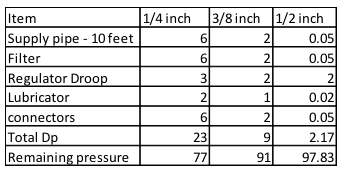
Then an adequate component size would be the 3/8-in. size.
Hi, I am currently hooking up a vacuum sealer that requires 6 cfm’s of air at 110 psi, the equipment will not complete it’s cycle & I believe the 1/4 npt FRC combo is causing the loss in pressure & the equipment drops to 90 psi in a dynamic running state. The equipment thus gets stuck in the middle of it’s cycle & cannot complete the sealing process because there is not enough vacuum being created. The house has 3-100 gallon compressors set at 135 psi the main piping is 1″ to the various departments & splits after the main into 1/4 npt size fittings & hoses. Will this piece of equipment require larger hoses & or FRC? Thx for any help, Scott