

 Perhaps you’ve tested your air tool and found that it is getting a much lower pressure that its rating. This could be causing sluggish performance and a lack of power, leading to lower productivity. With a little bit of research you can fix the problem by matching the correct hose and connector to the tool.
Often a facility will have a standard size connector and hose for all the tools in the plant. This might be adequate for very small tools, but if you have larger ones consuming more compressed air that average, you will run into problems.
The first thing to find out is the tool compressed air consumption and pressure rating. Most manufacturer’s instruction books or data sheets will show the compressed air consumption of the tool and the rated pressure, or you could measure it with a flow meter. Sometimes a manufacturer will give two flows, the actual cfm and the average cfm. Use the actual cfm when the tool is working. Let’s say we have a grinder that consumes 18 cubic feet per minute (cfm) at 90 psi.
Next we need to know the expected compressed air system operating pressure, let’s say the system runs at a pressure no lower than 105 psi. This means the maximum pressure drop in our supply components can be no more than 15 psi or the tool pressure will be lower than the tool rating of 90 psi.
 If we placed this tool on a 25 foot long section of ¼-in. hose, with two quick connect couplers, what kind of pressure drop would we expect? To estimate this, we need to look up the characteristics of our hoses and connectors. The following calculation is from an online calculator for Gates Corp. hoses that can be used as a rough estimate. There are other online calculators available that do the same calculation. We can see if we try to use a ¼-in. hose the hose pressure loss will be about 32 psi.
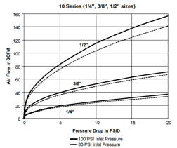
Then we might look up the pressure loss curve for our quick connect couplers and find that at 18 cfm flow the pressure loss of the two connections will be about 4 psi each, for a total of 8 psi. This hose sizing will cause a total pressure loss of 40 psi, resulting in a pressure of 65 psi at the tool, not the desired result.
Let’s calculate the pressure loss for the next standard size up, 3/8-in. connectors and hoses. We can see if we upsize the components the pressure loss in the hose will reduce to 3.8 psi and the connector loss will be about 1 psi per connector. Total pressure loss for 3/8-in. size will be 5.8 psi, which will provide adequate pressure of 99 psi to ensure the tool pressure is above its rating.
Of course there might be other components in the supply line, like pressure regulators and lubricators. Tool life can be reduce by operating at too high a pressure and without proper lubrication. These items will need to be studied too to ensure the final tool pressure is adequate.
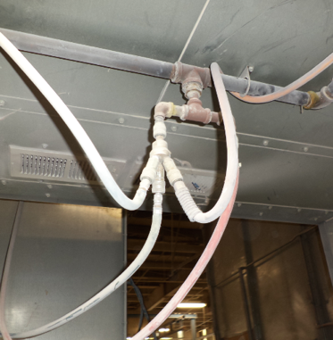
What about the connector in the picture at the beginning of the post. The use of a single ¼-in. connector to feed three separate ¼-in. supply lines resulted in very poor pressure and random very low pressure drips whenever two or more tools were used. We can see from the connector pressure loss chart that the loss per connector would exceed 20 psi if two 18 cfm tools were run at the same time.
Tool pressure loss problems can be solved with a little bit of research.
Leave a Reply