

The benefits of pneumatic power can be realized by following some basic pneumatic design rules for specifying air preparation units, actuators and valves.
Contributed by Chip McDaniel, Educational Specialist at AutomationDirect
Compressed air use by industrial machines is a close second to the use of electricity in terms of cost, and well ahead of other utilities such as water and natural gas in most plants and facilities. Electricity is less expensive per dollar of unit energy, but compressed air and pneumatics have other advantages encouraging their use.
This article will show why pneumatics is such a popular linear power option. Basic pneumatic valve selection will also be discussed—along with a primer on sizing pneumatic air preparation units, and selecting pneumatic valves and actuators.
Pneumatic advantages
Linear power transmission is typically done with fluid (pneumatic with air or hydraulic with oil) or electric power. Many vendors like to promote use of electrical actuators and their efficiency, yet simple and reliable pneumatic actuators and cylinders still often drive linear motion.
Pneumatic components are simple to work with, provide high-speed motion, are positionally repeatable, and are very reliable. Most maintenance personnel are comfortable or quickly trained in the use and troubleshooting of pneumatic valves and cylinders. The use of solenoids, cylinders and sensors is less complex than the electronics, gearboxes and other devices needed to convert motor rotation to linear motion.
Pneumatic hardware is also very affordable. Cylinders, solenoids, hoses and fittings can be purchased at a low cost. This simple pneumatic hardware and low purchase price also drive down the cost of maintenance.
Air cylinders and pneumatic actuators can also actuate and move very quickly when properly sized, and are easily adjusted using inline or cylinder-mounted flow control components. External hard stops or internal cushions provide repeatable positioning at a cylinder’s end of travel.
Pneumatic cylinders and actuators pack significant force in a small package. A typical one-inch cylinder can easily provide more than 100 lb of clamping force. This force is controlled by a simple manual valve, or a by a solenoid.
Pneumatic valve selection

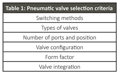
Fluid power control of pneumatic cylinders starts with proper valve selection to deliver clean and dry air to cylinders, actuators and nozzles. The pneumatic valve selection criteria listed in Table 1 helps with specifying the right valves to control air flow and cylinder activation within automated machines.
Many valve switching options are available. Directional control valves can be manually switched, but on automated machines solenoid-operated or air-piloted valves are more common.
Solenoid-operated and air-piloted valves are typically switched using 12 Vdc, 24 Vac/dc or 120 Vac power. In larger valve sizes, air-piloted valves are more electrically efficient as they switch a small valve spool, which then operates the much larger main valve spool.
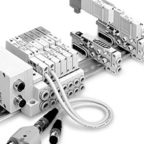
The simplest valves are 2-way, and there are also 4-way valves (Figure 2). These valve types are also often identified by their number of ports. All valves have an air in (P) port, and one air out (A) or two air out (A and B) ports. A valve may also have one or more exhaust ports. A 5-port valve can add a little confusion, but it’s technically a 4-way valve with two exhaust ports, labeled R and S, so the 5-ports are P, A, B, R and S. The two exhaust ports lead to the same place, open to the atmosphere, and are thus considered to be the same “way.”
A 2-position valve, as the name suggests, will be in one of two positions, open or closed. With 5-port, 2-position valves, the two output ports are always in opposite modes. When one is receiving inlet air, the other is exhausting air.
A 3-position valve has a center or neutral position that is either center closed and blocking all ports, or center exhaust with output ports connected to exhaust. The center-closed valve may be a good option to hold position or perform an inching operation of a cylinder. The center exhaust valve works well to dump air pressure from a cylinder when the actuator is not actuated, often for safety purposes.
What type of valve do you need? Generally, a 2-port valve would be used in an air blast application. A 3-port valve could pressurize a vessel, and then drain the pressure when switched. A 3-port valve is also used to control spring-return cylinders, with the spring retracting the cylinder when the valve is de-energized. A 5-port valve is often the best choice for controlling double-acting cylinders as it can pressurize and exhaust both sides of the cylinder for extension and retraction.
Valves are available in poppet, diaphragm and spool configurations. A poppet valve is often directly operated by a solenoid, with an example being a 2-way, 2-position gate valve. Diaphragm valves are like poppet valves but the diaphragm isolates the solenoid operating the valve from the fluid being switched. A direct- or pilot-operated spool valve uses a piston and seals to switch air and is commonly used in 4-way valves and 3-position valves.
A wide variety of form factors and valve integration methods are available. The ability to manifold-mount or stack valves is often important to simplify plumbing. Simplified wiring of the valves—using a single cable connected to a compact, modular valve bank—is another benefit and should be considered for all applications with multiple valves to avoid running many individual cables.
Air prep specification and sizing
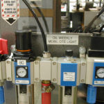
All machines and processes benefit from a supply of clean, dry air. This requires a suitable plant air supply at a consistent pressure, along with air prep at both the plant and machine level.
 Plant air should be connected to a manual, lockable air dump valve at the machine level. The machine air prep system should also include a filter regulator to remove water, dust and debris. A regulator is required to reduce the typical 100-130 psi plant air supply to a suitable machine control pressure of 60-90 psi. A pressure switch should also be used to ensure adequate pressure is available.
An electric soft-start valve is important as it both removes motion-causing air pressure from the equipment during an emergency stop, and slows the re-supply of air to the system when turning the equipment back on. This prevents unexpected fast cylinder motion that can cause banging and damage during machine startup.
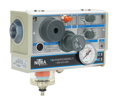
These air prep systems can be assembled by combining the dump valve, filter regulator and soft-start valve. A more convenient method is to use an all-in-one unit that also contains all the common air prep components along with an automatic drain air filter with a clogged filter indicator (Figure 1). These all-in-one air prep units reduce cost and installation space, while simplifying purchasing.
With any air prep system, air usage should be estimated before specifying the hardware. There are a variety of interactive tools online to estimate required air consumption.
The biggest consumers of air are the cylinders and air blast nozzles. Cylinder bore and stroke should be known, and air blast flow determined. When and how often the air is consumed by these devices is important as well. Users need to collect the data and size appropriately, and remember that the air is not all consumed at the same time.
Pneumatic actuator basics
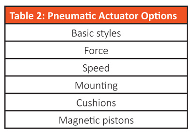
Pneumatic actuators come in many designs and sizes—and include a variety of mounting methods, internal features and options to provide a robust solution in industrial environments (Table 2).
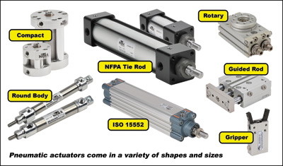
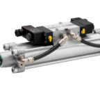
Many physical configurations and styles exist to enable a pneumatic actuator to fit into just about any machine or application (Figure 3). Some basic styles include compact, round body, tie rod, guided rod, rotary, ISO and gripper. A piston moving inside a cylinder is the most popular style with aluminum, steel, stainless steel or polymer body materials. Some can be disassembled and repaired, and others are non-repairable and must be replaced with a new unit if they fail. Single-acting cylinders with a spring return, and double-acting cylinders requiring a switched air supply and exhaust at each end of the cylinder, are available options.
Pneumatic actuator force and speed are a big part of the selection process, and the cylinder must be properly sized to meet design requirements. To start, use an online sizing software, such as AutomationDirect’s Interactive Cylinder Bore Calculator, when selecting an actuator. It’s good design practice to have about 25% more force available than calculated requirements.
 Speed is also an important design requirement, and there are many variables to consider. To see some rules of thumb, check out an online application such as AutomationDirect’s Interactive Theoretical Speed Table to help define required cylinder bore, system pressure and tubing.
If a specific cylinder speed is desired, it’s advisable to size the valve, tubing, fittings and cylinder for a faster stroke—and then use flow control valves to slow the cylinder down to the desired speed.
If extremely fast action is desired, some trial and error testing will probably be required, along with cushioned cylinders to prolong the life of the components in these high-speed systems.
There are many mounting options available including rod clevis, self-aligning rod coupler, rod eye, pivots, mounting brackets and flanges. Internally, end-of-travel cushions smooth the last half inch or so of cylinder travel, help prevent pounding the end caps off a cylinder, and prevent damage/wear/tear to connected mechanical apparatus. Another internal feature is the use of magnetic pistons, which allow magnetic proximity sensors to be easily mounted to the cylinder wall to sense actuator position.
Carefully specify the pneumatic air preparation systems, the valves and the actuators—and add hose, fittings, flow controls and sensors. The result will be a simple, cost effective and robust solution to meet your linear motion needs.
AutomationDirect
AutomationDirect.com
I have a motorcycle lift (table) and need to know what kind of valve I need. The cylinder goes up with air pressure supplied and goes down when the air is exhausted, I need the lever go one way to apply air and the other way to exhaust the air and hold (no air applied or exhausted) position in the center lever location. In 1/4 or 3/8 threaded for fittings.
I have mixer gates using two cylinders, when power off time ,air becomes that times gates will be it’s becomes improper mixing ,I need the cylinder doesn’t when no air time
David, a standard 2 position, hand lever controled, 2 way air valve
Need help with level control. I have a tank with a Lo level switch and a hi level switch operating a 3 way dump valve that is spring return to non dump position. I need a pneumatic circuit that will operate the dump valve when the Hi level is tripped but not shut the valve off (Remove air) until the Lo level switch is tripped.