

by Jerry Walling, Marketing and Business Development, Fabco-Air Inc.
Learn how to choose the perfect actuator for your next compressed air system.
Air cylinders are the workhorses of many automation applications. They’re offered in a variety of industry standards—and they come in an assortment of shapes, sizes and types, not to mention with numerous optional features. The number of permutations can be a bit overwhelming. The good news is that each pneumatic actuator type and configuration has a place in today’s motion-centric automation environment.
Even though the air cylinder market includes a multitude of standard options, pneumatic actuators are still selected by their ability to perform a specific function. These functions are virtually endless. Common air cylinder applications include:
• opening and closing the gate on a knife gate valve
• allowing motion and movement in the animatronics industry
• diverting goods on a conveyer system
• raising and lowering rides at a amusement park
• operating gates to rapidly unload a railcar commodity
• press operation in the dry cleaning industry
• brush movement in the auto wash industry
In order to properly specify an air cylinder for any application, you must answer two questions before moving into the heart of the design. The first is: What do I need the cylinder to do/what type of work will it be performing? The second is: What types of cylinders do I have to select from?
Push and pull forces
You’ll need to determine the force required to size the cylinder properly. When the force is known, you can determine the bore size or the power factor (effective piston area) of the cylinder you need by using the equation:
Force =(Pressure Available) x (Power Factor)
or re-stated
Power Factor = Force ÷ (Pressure Available)
In this calculation, we have not considered any safety factors. As a starting point, let’s use a 50% factor of safety. Therefore, multiply our Cylinder Power Factor above by 1.5 and use the result to calculate the required cylinder bore from the equation:
(Cylinder Power Factor) x 1.5 = π(Bore)2 ÷ 4.
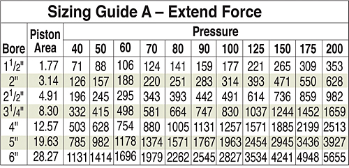
Or we can find the appropriate bore using force factor tables in the manufacturers’ catalogs as shown below in a typical example. Here, Figure 1 shows the actual piston area and the extend forces obtainable from various air pressures.
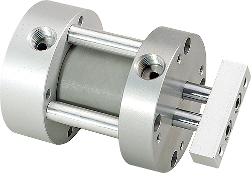
Pulling force, calculated when the cylinder retracts, brings the rod diameter into account. As shown below, air pressure can act only on part of the piston in retract mode because the rod blocks the center portion of the piston. Thus, the retract power factor is calculated as an annular ring—the piston area minus rod area.
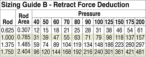
Again, helpful tables from cylinder catalogs give rod areas to speed your calculations of “pulling” power factors. (Shown in Figure 2 below.)
If you do not have enough pressure to produce the desired force using the preferred bore size cylinder, then you must go to a larger unit. This will affect the package size and may create some space requirement issues, so there is generally a balance that must be achieved.
The cylinder stroke
What stroke do you need? Pulling a load might require a 15-ft stroke if you’re closing the door to a large oven. Lifting a stop gate on a conveyor could require only a 2-in. motion, whereas pushing a load off of the conveyor might require 30 in. or more. Staking a rivet wouldn’t require much stroke at all—most likely only a fraction of an inch.
Whatever your task, knowing the stroke starts to define the type of cylinder you’ll need and the envelope size required for mounting it. For purposes of discussion here we classify and show examples of four cylinder types by stroke as follows: (a) short stroke, (b) intermediate stroke, (c) long stroke, and (d) specialty stroke cylinders. Note that some cylinders may overlap all of the categories.
Short stroke, compact cylinders: These come in a variety of body styles and have strokes as short as 1⁄16-in. with bores down to 1⁄2-in.
Intermediate stroke: We define these as cylinders having strokes to 36 in. After World War II, fast acting, light duty automation applications gave rise to compressed air as an alternative to hydraulics. The then popular tie-rod cylinder construction was copied using aluminum wherever possible to reduce weight and cut manufacturing costs.
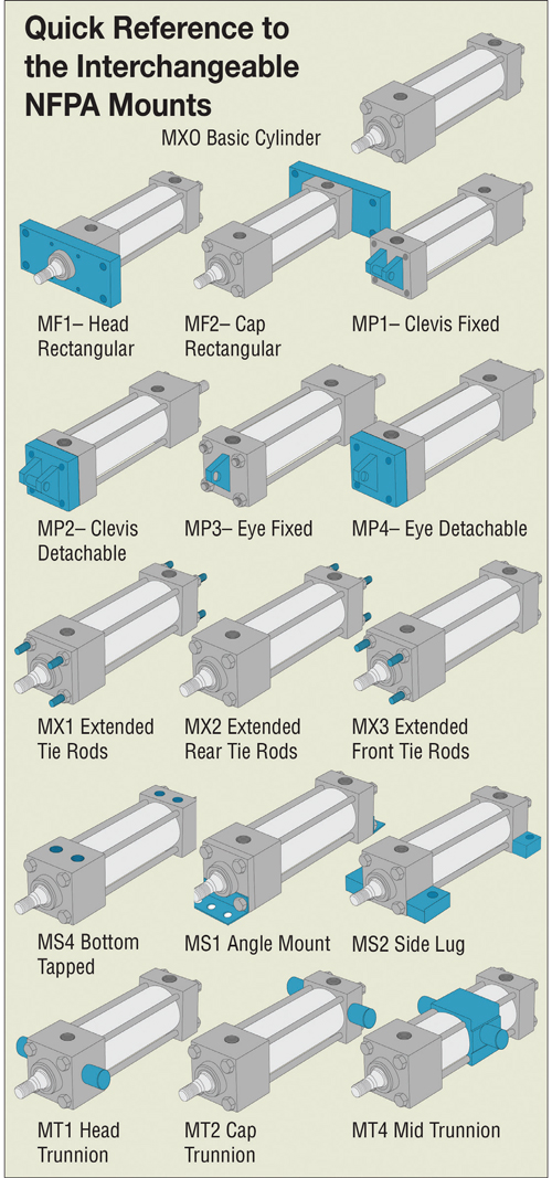
Long stroke: We are showing NFPA interchangeable cylinders in this category, because their upper stroke limit is 99 in. But, they are well adapted to applications calling for strokes from 4 in. and up. Magnetically coupled (rodless) cylinders have strokes to about 40 in.
Specialty stroke: Cable cylinders, made by several manufactures, are one example of specialty cylinders. As can be seen from the basic drawing, a clamp can be pulled left or right by a cable attached to the cylinder’s piston. A 15-ft stroke cable cylinder could be used to control the 15-ft oven door we mentioned earlier. Because the cable can be any length we want, the cylinder can be mounted anywhere that is convenient for your design—directly on the oven or across the room from it if necessary. Cable cylinders can have strokes of more than 25 ft and may be located remotely from the workload.
Specialty cylinder applications
Now that you have addressed the preliminary questions and found no standard cylinder to meet your specific requirements, you’re left with a few more questions:
What type of cylinder best suits my needs? When designing in a custom cylinder, it’s easier if you start with a particular family of cylinders, such as NFPA Interchangeable, compact or non-repairable, which will be conducive to your application.
Is the application heavy duty? Is there plenty of room available? If the answer is yes, then you may wish to start with an NFPA style cylinder.
Is real estate at a premium? If that’s the case, then you may be forced into starting with a compact style.
Is price the main concern? If so, then a non-repairable unit may become your first choice.
Remember that you do have several choices. Once you have determined the style of cylinder, you can get to the details of your design.
Mounting considerations
You probably know how you plan to mount the unit. But often times, you find that mounting will require a special bolt pattern or mounting style that is non-standard. You’ll have to ask how the style of cylinder you have selected can be modified to fit the pattern for a minimum cost. Will it require that special parts be manufactured? Will it need unique mounting hardware, such as plates, flanges or brackets?
In cases where the mount is built into or uniquely attached to your cylinder, costs will increase along with manufacturing lead times.
As an example, nose mounting might require that unique end caps be produced. Integral lug mounts could require special extrusions, welding or other creative attachment concept to be employed. In lieu of lugs, is there room to drill and tap your cylinder’s end caps (or body) with special bottom or side mounting holes? Would you have enough depth of thread?
Conclusion
There are still other issues for the design engineer to consider. You’ll need to determine whether there are special movements, sensing, or side loads being applied. Any of these may require special modifications to the cylinder. Will the load stop at any intermediate position? Can the load be allowed to rotate slightly? Will you need position sensing? Are there heat issues? Discussing these types of issues with a manufacturer or technical sales engineer can help to further refine the choice of cylinder.
Fabco-Air Inc.
www.fabco-air.com
Leave a Reply