

Functional safety features in pneumatic machines and systems are critical in reducing the risk of injury without impacting operational efficiency and productivity. Designers of functionally safe pneumatic systems have put in fail-safe mechanisms to detect potentially dangerous conditions and to activate a protective or corrective device, such as a pneumatic rod lock, that will prevent or reduce consequences of a hazardous event.
A pneumatic cylinder stopping method should always include redundancy, such as a mechanical lock, should there be a component failure in the circuit. Pressure trapped within a pneumatic circuit is a potential safety hazard, so the circuit design must account for the controlled release of trapped energy. This trapped energy could create unplanned motion, expulsion of piston rods or sequence mis-mating that could result in damage or a hazard.
It is imperative system designers use a safe methodology like ISO 13849-1 or EN/IEC 62061.
According to the International Electrotechnical Commission (IEC) the IEC 62061 standard specifies requirements and makes recommendations for the design, integration and validation of safety-related electrical, electronic and programmable electronic control systems (SRECS) for machines. Meanwhile, the International Standards Organization (ISO) EN/ISO 13849-1:2005 standard provides safety requirements and guidance on the principles for the design and integration of safety-related parts of control systems (SRP/CS) — including the design of software. For these parts of SRP/CS, it specifies characteristics that include the performance level required for carrying out safety functions. It applies to SRP/CS for high demand and continuous mode, regardless of the type of technology and energy used (such as electrical, hydraulic, pneumatic, or mechanical) for all kinds of machinery.
 For more on these standards, visit our sister site, motioncontroltips.com.
Most functional safety certified linear brakes for pneumatic rod cylinders employ spring-set pneumatically released friction action. Here the friction surfaces clamp (via a friction element called a clamping collar) the assembly’s linear rod for safe holding or emergency stopping. As with brakes for motor-based linear motion, some of these linear brakes achieve higher functional-safety ratings by integrating one or two magnetic proximity sensors. An additional benefit to these brakes is how the linear brake uses the same disengagement power source (that of pneumatics) as the rod actuator… allowing use of similar components. What’s more, linear brakes in cylinder-mount configurations let OEMs set up the axis to let one common controller execute commands over both components.
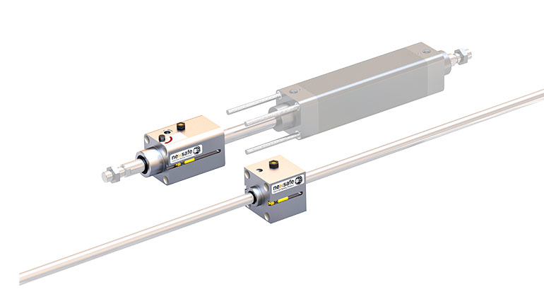
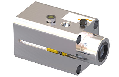
Pneumatic rod locks from Nexen have been developed for locking and holding on the shaft of an air cylinder or guide rod. These spring-engaged, air-released units are designed to hold in a safe position by default. Brakes are intended for static holding applications and Emergency Stop situations.
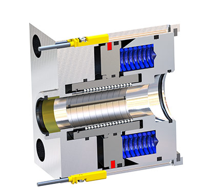
They use a series of equally spaced compression springs to provide the rod lock actuating force. Dozens of ball bearings separate a split, tapered collar and piston. The piston travels up the ramp on the collar under the spring force and causes the split collar to constrict on the rod. Air pressure applied to the opposite side of the piston compresses the springs to release the grip on the road.
Select models have a manual release feature to disengage the rod lock without air pressure. The mechanism is cam operated, turned with a wrench and is a default-to-lock function. As long as a force is applied to the wrench, the road lock is disengaged. With no force applied, the rod lock defaults to the engaged position.
Nexen
nexen.com
Leave a Reply